9:53
Syllabus of Microprocessor KCS403 | Introduction of KCS403
10:31
important topics of microprocessor | KCS 403 | AKTU exam
10:04
unit 1L1 | Microprocessors Evolution and Types | Evolution of microprocessors
6:32
unit 1 L2 | Define Microprocessor & Microcontroller
3:48
Unit 1 L3 | Difference between Microprocessor and Microcontroller
11:52
Unit 1 L4 | Address Bus | data bus | control bus | Bus Structure of 8085 Microprocessor
8:25
U1 L20 | Address and Data Line Finding of Memory Unit | find the number of address and data lines
2:39
U1L21 | Number of Memory Chips Required to Construct A Memory | Number of chips required for 128KB
3:23
U1 L23 |Find the Starting Memory address | memory address of Memory | How to find starting address
3:24
U1L24 | Find last address of memory when first Address and Memory Size is Given | Last location
2:33
U1 L25 | Memory size calculation when first and last location is given | Memory size calculation
14:12
Unit 2 L17.1 | Interrupts in 8085 microprocessor | Types of interrupts | 8085 Interrupts
5:19
U2 L17.3 | Interrupt Address Calculation in Microprocessor 8085 | Vector interrupts of 8085 MPU
9:13
Unit 2 L18 | SIM | Set Interrupt Mask | Interrupts in 8085 Microprocessor |SIM instruction
7:49
Unit 2 L19 | RIM instruction | Read Interrupt Mask| RIM IN 8085 MICROPROCESSOR | Pending Interrupt
14:37
Unit 2 L17.2 | 8085 Interrupts | interrupt structure of 8085 microprocessor
Unit 1 L11 | Data flow from memory to MPU | Fetch operation in 8085 Microprocessor| opcode fetch
13:01
Unit1 L18 | Logic devices for interfacing in microprocessor | Interfacing devices in Microprocessor
20:28
Unit 1 L7 | Pin Diagram of 8085 Microprocessor | Pin Description of 8085 Microprocessor
21:24
U1 L6 | 8085 Architecture | Block diagram of 8085 | Internal Architecture of Microprocessor 8085
12:22
Unit 1 L5 | 8085 Registers | Registers of 8085 | Accumulator | Flag Register | Stack Pointer
4:49
Unit 1 L10.1 | PSW of 8085 MPU |Program status word of 8085 in hindi | Flags of 8085 microprocessor
12:24
U1 L9.2 | Example of Flag Calculation of 8085 microprocessor | Flags of 8085 microprocessor
11:13
Unit 1 L8 | Demultiplexing of Address/Data Bus in 8085 Microprocessor | Demultiplexing
7:11
U1L10| Control signals of 8085 | Generation of Control signal In 8085 microprocessor
9:31
U1 L12 OPCODE FETCH Timing diagram in 8085 Microprocessor | Timing Diagram for 8085 microprocessor
13:13
Unit 1 L16 | Timing diagram for MVI A,8 bit Data in 8085 | Draw timing diagram for MVI A,32H
5:14
Unit1 L15| Instruction cycle | Machine Cycle | T state
6:01
U1L13.1 | Memory Read operation| 8085 microprocessor | Memory Read operation in 8085 microprocessor
8:45
Unit 1 L13.2 |Timing Diagram for Memory Read of 8085 Microprocessor | Memory Read timing diagram
4:51
U1 L14.1|Memory Write Operation In 8085 Microprocessor | Memory Write cycle |Memory Write operation
8:26
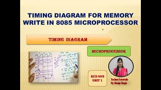
Unit 1 L14.2 | Timing diagram for memory write cycle in microprocessor 8085| Timing diagram for 8085
8:54
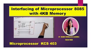
U1 L31 | Interfacing of 8085 Microprocessor with 4KB memory | Memory interfacing with 8085 MP
8:39
U1 L26 | Address Decoding | MemoryMapping | memory interfacing example
16:24
U1 L19| Memory interfacing | connect 8 K byte memory to 8085 Microprocessor | Address decoding
12:21
U1 L19 | Timing diagram for IN 64 H of 8085 microprocessors | Timing diagram of IN Instruction
8:34
Unit1 L27 | Input Interfacing | Input output mapped IO Interfacing | Interfacing of DIP Switches
9:00
U2 L28 | Input Output interfacing in 8085 | IO mapped Interfacing| Interfacing in 8085
17:06
Unit 1 L 18 | Timing Diagram for STA of 8085 Microprocessor | Timing Diagram of STA Instruction
12:47
U1 L29 | Memory Mapped I/O Interfacing | Interfacing in 8085 Microprocessor
16:31
U1 L32 | Memory interfacing 16K Byte EPROM and 8K byte RAM with 8085 microprocessor | 3(a)
2:12
U2L15.3 | Find the address of input and output port | IO mapped input/output interfacing
9:07
unit1 L30 | Difference between Memory Mapped I/O and Peripheral I/O | Memory Mapped IO
13:16
Unit 2 L 1 | Addressing Modes | Addressing Modes of Microprocessor 8085 | 8085 addressing modes
5:22
U2 L2 |Types of instructions of Microprocessor 8085| Instructions word size in 8085 Microprocessor
13:40
Unit2 L3 | Data Transfer Instruction in 8085 Microprocessors | 8085 Data transfer instruction
7:30
U2 L16 | IN & OUT instruction in 8085 microprocessor | Data transfer instruction of 8085 MP
13:57
U2 L4 |Arithmetic instructions of 8085 Microprocessor| instructions of 8085 MPU| 8085 instruction
19:37
Unit2 L5 | Logical instructions of 8085 microprocessor | Bit Manipulation Instruction of 8085
13:33
unit 2 L6 | Branch instructions | Jump | Call and return instructions | Restart instructions
5:15
Unit 2 L18 | Assembler Directives of 8085 Microprocessor | Assembler Directives
29:55
Unit 3 L3| 8086 Pin Diagram | Microprocessor 8086 | Minimum/maximum mode Pin in 8086 microprocessor
24:08
Unit 3 L 2 | 8086 Block Diagram | The architecture of 8086 microprocessors
8:38
Unit 3 L 1 | Difference between 8085 and 8086 Microprocessor | 8085 Vs 8086 Microprocessor
3:41
Unit 3 L4 | Effective address in 8086 Microprocessor | Physical Address Calculation in 8086 MPU
17:28
Unit 3 L5 | Flag register of 8086 Microprocessor | 8086 Flag register | 8086 Microprocessor
16:39
Unit 3 L 6 | Flag register of 8086 | Example of Flag register of 8086 | PSW of 8086
14:03
Unit 3 L7 | Memory segmentation in 8086 Microprocessor | Memory Segment in 8086 Microprocessor
14:05
U3 L8.1 | 8086 minimum mode | Minimum mode configuration of 8086 | operating mode of 8086
12:33
unit 3 L8.2 | Maximum mode of 8086 | maximum mode configuration of microprocessor 8086
20:01
U3L7.1 | Addressing Modes of 8086 Microprocessor | 8086 Addressing Mode | 8086 microprocessor
21:42
U1L28 | Interrupts in 8086 | Interrupt service routine | Interrupt Vector table of 8086| Interrupts
19:29
U3 L10 | Instruction Format of 8086 Microprocessor | Instruction Templates for 8086 Microprocessor
16:13
Unit 2 L11 | 8 Bit addition program Using 8085 Microprocessor | addition Program
7:05
Unit 2 L 13 | Program for two 8 bit Subtraction in 8085 Microprocessor | 8085 Programming
18:48
U2 L14|Program for multiplication in 8085 Microprocessor | Multiplication ALP in 8085 microprocessor
18:56
Unit 2 L15 | Program for Division in 8085 Microprocessor | Division program using 8085 MPU detailed
5:59
Unit 4 L5 | Program for addition of Two 16 bit Numbers in 8086 Microprocessor | method 1
7:03
Unit 4 L6 | 8 bit subtraction Program in 8086 Microprocessor | 8086 Microprocessor Programming
5:48
Unit2 L13 | Time delay calculation in 8085 microprocessors |easy way to fast time delay calculation
3:07
U2 L14 | Find Count Value for given time Delay in 8085 Microprocessor| Time delay Example of 8085 MP
15:34
Unit 2 L7 | Rotate Accumulator (RRC,RLC,RAR,RAL) instructions in 8085 | 8085 rotate instructions
10:41
U2 L8 | Stack in 8085 Microprocessor |stack instructions in 8085 Microprocessor | stack Operation
16:54
U2 L9 | PUSH & POP Instructions in 8085 Microprocessor | Stack Instructions in 8085 | PUSH | POP
7:41
Previous year paper questions | Example: program of Push & POP | Content of HL pair after execution
8:09
unit 3 L9.1 | Direct Memory Access- DMA | DMA controller interconnections for microprocessor system
17:22
Unit 3 L9.3 | DMA 8237 | Pin diagram of 8237 | Pin description of DMA controller 8237
18:54
Unit 3 L9.2 | 8237- Block diagram | Block diagram of 8237 DMA controller | Block diagram of 8237
10:22
Unit 3 L10.1 | 8255 Pin Diagram | Pin Configuration of 8255 | PPI (Programmable Peripheral Interface
11:16
unit 3 L10.2 | 8255 PPI | Block Diagram of 8255 (Programmable Peripheral Interface)| Port address
4:17
Unit 3 L10.3 | Port Address Calculation in 8255 PPI | Port address Calculation
7:36
Unit3 L10.4 | Operating Modes of 8255 | Modes of PPI | Modes of Programmable Peripheral Interface
11:08
U3 L10.5 |Control word format of 8255 | I/O Mode Control word format 8255 | control register of 8255
5:20
Unit 3 L10.6 | BSR mode of 8255 | operating mode of 8255 | BSR mode of PPI
9:05
U3 L7 | BSR Mode example| Subroutine for 10 msec delay| Bit set reset mode Subroutine | AKTU 16-17
8:11
U3 L11.1 | 8254/8253 PIT|Pin diagram of 8254|Programmable interval timer|difference of 8253 & 8254
6:48
U3 L11.2 | 8254/8253 PIT | Internal architecture of 8254 | Block Diagram of 8254 | PIT
U3 L11.3 | Code word register of 8254 | Code word format of 8254 | PIT
18:37
U3 L11.4 |Modes of operation of 8254| Operating Modes of 8254| Modes of 8254|operating modes of 8253
7:22
Unit 5 L 3.5 | Program for square wave generation in 8254 | AKTU 2016-17
12:46
Unit3 L12.1|8259 PIC | Programmable interrupts controller | Introduction | Pin configuration of 8259
17:51
U3 L12.2 | 8259 Programmable Interrupt controller| Architecture| Block diagram | Interrupt operation
5:54
Unit 3 L12.3 | Modes of 8259 | Operating Modes of 8259 | Priority Modes of 8259
20:35
U3L13 | 8251 | USART |Block diagram of 8251| Universal synchronous asynchronous receiver transmitter
11:03
Unit 3 L14 | RS232 | RS232C in Microprocessor
10:34
Program to transfer a Block of Data byte in 8085 Microprocessor | Block transfer program in 8085
20:26
Zero to nine counter program in 8085 | BCD counter Program using 8085 microprocessor
38:40
One shot video | Unit 1: part 2 | BEC502 | MPMC | 8085 PIN digram & block digram in one shot